VLAN concepts may be a bit overwhelming at first, but surprisingly the actual configuration of VLANs in a network of Cisco switches requires just a few simple steps:
Step 1 Create the VLAN.
Step 2 Assign switch ports to that VLAN.
In Example 7-2, we will create several new VLANs on Switch1 and also assign names to them according to Table 7-1.
Table 7-2 VLANs to be created
| VLAN IDs | Names |
| 10 | Engineering |
| 20 | Finance |
| 30 | Management |
| 40 | Marketing |
| 50 | Sales |
We start out by displaying existing VLANs on the switch using command show vlan brief. The switch displays VLANs 1, 1002, 1003, 1004, and 1005 which are created by default on Cisco switches and cannot be removed. As we have not created any new VLANs yet this output is just what we expect.
Now we create new VLAN IDs 10, 20, 30, 40, and 50 with names Engineering, Finance, Management, Marketing, and Sales respectively. Please note that we have assigned names to VLANs but this step is optional. If names are not explicitly assigned to VLANs, a Cisco switch automatically creates a VLAN name for each VLAN created which is drawn from the VLAN ID itself.
Enter configuration commands, one per line. End with CNTL/Z.
Switch1(config)#vlan 10
Switch1(config-vlan)#name Engineering
Switch1(config-vlan)#vlan 20
Switch1(config-vlan)#name Finance
Switch1(config-vlan)#vlan 30
Switch1(config-vlan)#name Management
Switch1(config-vlan)#vlan 40
Switch1(config-vlan)#name Marketing
Switch1(config-vlan)#vlan 50
Switch1(config-vlan)#name Sales
Switch1(config-vlan)#exit
Switch1(config)#exit
Switch1#
Now we display VLANs again just like we did at the start to verify that new VLANs have been created using the show vlan brief command.

You can see that five new VLANs have been successfully created but also note carefully in the Ports column that now switch ports are yet assigned to these newly created LANs.
Now we will proceed to assigne switch ports to VLANs.
Table 7-3 Ports to be Assigned to VLANs
| VLAN IDs | Ports |
| 10 | Fa0/1, Fa0/2, Fa0/3 |
| 20 | Fa0/4, Fa0/5 |
| 30 | Fa0/6 |
| 40 | Fa0/7, Fa0/8 |
| 50 | Fa0/9, Fa0/10 |
We are going to assign switch ports FastEthernet 0/1 to FastEthernet 0/3 to VLAN 10.
Switch1(config)#interface FastEthernet 0/1
Switch1(config-if)#switchport access vlan 10
Switch1(config-if)#switchport mode access
Switch1(config)#interface FastEthernet 0/2
Switch1(config-if)#switchport access vlan 10
Switch1(config-if)#switchport mode access
Switch1(config)#interface FastEthernet 0/3
Switch1(config-if)#switchport access vlan 10
Switch1(config-if)#switchport mode access
Now assign switch ports FastEthernet 0/4 and FastEthernet 0/5 to VLAN 20.
Switch1(config-if)#switchport access vlan 10
Switch1(config-if)#switchport mode access
Switch1(config)#interface FastEthernet 0/5
Switch1(config-if)#switchport access vlan 10
Switch1(config-if)#switchport mode access
We will continue by assigning port FastEthernet 0/6 to VLAN 30.
Switch1(config-if)#switchport access vlan 30
Switch1(config-if)#switchport mode access
Let’s assign switch ports FastEthernet 0/7 and FastEthernet 0/8 to VLAN 40.
Switch1(config-if)#switchport access vlan 40
Switch1(config-if)#switchport mode access
Switch1(config)#interface FastEthernet 0/8
Switch1(config-if)#switchport access vlan 40
Switch1(config-if)#switchport mode access
Now assign switch ports FastEthernet 0/9 and FastEthernet 0/10 to VLAN 50.
Switch1(config-if)#switchport access vlan 50
Switch1(config-if)#switchport mode access
Switch1(config)#interface FastEthernet 0/10
Switch1(config-if)#switchport access vlan 50
Switch1(config-if)#switchport mode access
Switch1(config-if)#exit
Switch1(config)#exit
Switch1#
The command show vlan brief is turning out to be really useful we can use it yet again here to verify that switch ports have been assigned to VLANs as expected.

This completes our configuration and verification for this section but you may have noticed that there is quite a bit of repetition when it comes to assigning several switch ports to the same VLAN. There is a shortcut Cisco IOS provides to accomplish this with fewer commands by applying those commands to a range of switch ports. Lets again assign switch ports FastEthernet 0/1 to FastEthernet 0/3 to VLAN 10 using the new method.
Switch1(config)#interface range FastEthernet 0/1 – 3
Switch1(config-if)#switchport access vlan 10
Switch1(config-if)#switchport mode access
As you can see it greatly reduces the effort needed to apply the same configuration to multiple switch ports. This method can be used to easily apply any commands from the interface configuration mode to a range of interfaces.
Please keep in mind that Cisco IOS switches keep VTP and VLAN information in a file named vlan.dat which is stored in the flash memory. Even if you erase the startup configuration and reload the device, VLAN information persists because it is saved in vlan.dat file. You must manually delete the vlan.dat file in addition to erasing the startup configuration if you want to get rid of all VLAN information on the switch.

VLAN Management Policy Server (VMPS)
Cisco switches also support a dynamic method of assigning devices to VLANs, based on the device’s MAC addresses, using a tool called VLAN Management Policy Server (VMPS). A VLAN Management Policy Server or VMPS is simply a Cisco switch that maintains device information to VLAN mapping. With VMPS, a switch administrator can dynamically assign a network device to a particular VLAN. This technology ties VLAN membership to the end device rather than the switch port and is useful in sites that contain a large number of mobile users.
You can use the VLAN Management Policy Server (VMPS) service to set up a database of MAC addresses to be used for the dynamic addressing of your VLANs. The VMPS database automatically maps MAC addresses to VLANs. A dynamic access port can belong to one VLAN anywhere in the range 1-4094 and is dynamically assigned by the VMPS. Lower end switches like the Catalyst 2960 can be a VMPS client only.
Trunk Port Configuration
You can manually configure trunk links on Cisco switches but Cisco has also implemented a proprietary, point-to-point protocol called Dynamic Trunking Protocol (DTP) that negotiates a common trunking mode between two neighboring switches. The negotiation covers the encapsulation (ISL or 802.1Q) and whether the link becomes a trunk at all. This allows trunk links to be used without much manual configuration or administration.
Now that you understand the two types of trunk interfaces, let’s see how to configure each type. The following list describes the different options available to you when configuring a switch interface:
switchport mode access This command entered in interface configuration mode puts the interface into permanent non trunking mode and also negotiates to convert the link into a non trunk link. The interface becomes a non-trunk interface regardless of whether the neighboring interface is also a non-trunk interface. Such interface would be a dedicated layer 2 interface.
switchport mode dynamic auto This interface configuration mode command makes the interface able to convert the link to a trunk link dynamically only if the neighboring switch initiates DTP negotiation. The interface becomes a trunk interface if the neighboring interface is set to trunk or dynamic desirable mode. This is also the factory default mode on Cisco switch interfaces.
switchport mode dynamic desirable This interface configuration mode command makes the interface able to convert the link to a trunk link dynamically by actively initiating DTP negotiation. The interface becomes a trunk interface if the neighboring interface is set to trunk, dynamic desirable, or dynamic auto mode.
switchport mode dynamic desirable This command puts the interface into permanent trunking mode also negotiating to convert the neighboring interface into trunking mode. The interface becomes a trunk interface even if the neighboring interface is not a trunk interface.
switchport nonegotiate This interface configuration mode command prevents the interface from generating DTP frames to negotiate trunking. You can use this command only when the interface is configured with switchport mode trunk or switchport mode access. This command is not compatible with dynamic auto and dynamic desirable modes.
Dynamic Trunking Protocol (DTP) is not only used to negotiate trunking on a link between two devices but also to negotiate the encapsulation type of either 802.1Q or ISL. When we decide to make a link access or trunk using relative configuration commands, it is a good practice to disable DTP on the link by using switchport nonegotiate command to prevent unnecessary DTP traffic on the link.
Table 7-4 Trunk Configuration Options
| Configuration Command | Short Name | Meaning | Configuration on Other Side to Trunk |
| switchport mode trunk | Trunk | Always trunks; sends DTP messages to help other side choose to trunk | On, desirable, auto |
| switchport mode trunk;switchport nonegotiate | Trunk (with nonegotiate) | Always trunks; does not send DTP messages | On |
| switchport mode dynamic desirable | Desirable | Sends DTP messages and trunks if negotiation succeeds | On, desirable, auto |
| switchport mode dynamic auto | Auto | Replies to DTP messages and trunks if negotiation succeeds | On, desirable |
| switchport mode access | Access | Never trunks; sends DTP messages to help the other side reach the same conclusion | Never trunks |
| switchport mode access;switchport nonegotiate | Access (with nonegotiate) | Never trunks; does not send DTP messages | Never trunks |
Please see below diagram where SW1 is connected to SW2, SW3, and SW4 via interface Fa0/13, Fa0/16, and Fa0/19 respectively. Also note that SW2, SW3, and SW4 each has its interface Fa0/13 connected to an interface on SW1. This is how we are going to configure our switched network here:
- SW1 – SW2 configured as ISL trunk
- SW1 – SW3 configured as 802.1Q trunk
- SW1 – SW4 configured dynamically by DTP
Figure 7-10 Trunking Configuration Reference for Example

We start out by configuring interface FastEthernet 0/13 of SW1 as trunk and setting the encapsulation to ISL.
SW1(config-if)#switchport trunk encapsulation isl
SW1(config-if)#switchport mode trunk
We now configure interface FastEthernet 0/16 of SW1 as trunk and set the encapsulation to 802.1Q.
SW1(config-if)#switchport trunk encapsulation dot1q
SW1(config-if)#switchport mode trunk
We will not change the default configuration on interface FastEthernet 0/19 of SW1 and let Dynamic Trunking Protocol (DTP) negotiate trunking with interface FastEthernet0/13 of SW4.
Now we move to SW2 and configure interface FastEthernet 0/13 as trunk and set the encapsulation to ISL.
SW2(config-if)#switchport trunk encapsulation isl
SW2(config-if)#switchport mode trunk
Now we move to SW3 and configure interface FastEthernet0/13 as trunk and set the encapsulation to 802.1Q
SW3(config-if)#switchport trunk encapsulation 802.1q
SW3(config-if)#switchport mode trunk
We will not change the default configuration of interface FastEthernet0/13 of SW4 and let it negotiate trunking with interface FastEthernet0/19 of SW1 by Dynamic Trunking Protocol (DTP).
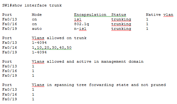
Now that out trunking configuration is complete on all switches, let’s move to SW1 and see if trunks have been formed as expected.

In the above output of command show interface trunk on SW1, you can see three interfaces listed in Port column as expected. You can see in Mode column that Fa0/13 and Fa0/16 are in on mode while Fa0/19 is in auto mode. This is consistent with the fact that Fa0/13 and Fa0/16 are manually configured as trunks while Fa0/19 has DTP running on it. We move on to the Encapsulation column now where you see the encapsulation for Fa0/13 and Fa0/16 is isl and 802.1q respectively. The encapsulation for Fa0/19 is listed as n-isl or negotiated ISL. This means DTP was running on this interface and the negotiation resulted in formation of a trunk with ISL encapsulation.
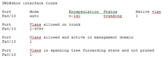
We move to SW2 now and see how trunks have formed.

We move now to SW3 and verify trunking.

Finally, let’s move to SW2 and see how trunks have formed.

That was one doozy of an example, but we learnt how to create and verify trunking using different methods. There is some additional fine tuning that can be done to the trunk links as shown below:
allowed Set allowed VLAN characteristics when interface is in trunking mode
encapsulation Set trunking encapsulation when interface is in trunking mode
native Set trunking native characteristics when interface is in trunking mode
pruning Set pruning VLAN characteristics when interface is in trunking mode
Defining the Allowed VLANs on a Trunk
By default the full range of VLANs 1 to 4094 are allowed on a trunk link. But you can selectively allow VLANs on a trunk while disallowing others using command switchport trunk allowed vlan:
SW1(config-if)#switchport trunk allowed vlan ?
WORD VLAN IDs of the allowed VLANs when this port is in trunking mode
add add VLANs to the current list
all all VLANs
except all VLANs except the following
none no VLANs
remove remove VLANs from the current list
SW1(config-if)#switchport trunk allowed vlan 1,10,20,30,40,50
The above command will only allow VLANs 1,10, 20, 30, 40 and 50 on the trunk while disallowing all others. The configuration can be verified using command show interface trunk:

Modifying the Trunk Native VLAN
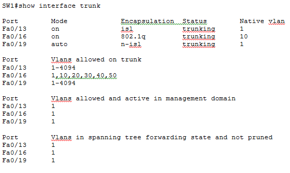
The native VLAN is the one VLAN whose frames are not tagged with 802.1Q encapsulation before sending out an 802.1Q trunk. The native VLAN should match on both ends of a trunk link because the receiving end would interpret any frame received untagged on an 802.1Q trunk as belonging to the native VLAN. You can change the native VLAN using command switchport trunk native vlan.
We change the native vlan first on Fa0/16 of SW1 and then on Fa0/13 of SW2 to complete the configuration.
SW1(config)#interface Fa0/16
SW1(config-if)#switchport trunk native vlan 10
SW2(config)#interface Fa0/13
SW2(config-if)#switchport trunk native vlan 10
You can verify the configuration using the good old show interface trunk command on SW1 and SW2. The output on SW1 looks something like:


