Single Subnet for all Routers
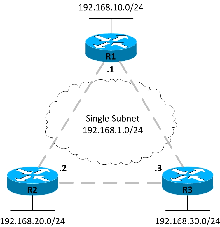
The first approach is to use a single IP subnet for the whole Frame Relay network, as shown in Figure 12-12.
Figure 12-14 Single Subnet for all Routers

The single-subnet option is normally used when there is a full mesh of virtual circuits (VCs). In a full mesh, every router has a virtual circuit to every other router, which means that every router can send frames directly to every other router. This addressing scheme resembles Ethernet LANs with the difference that IP addresses are configured on the serial interfaces of routers with Frame Relay encapsulation. The single-subnet option is conceptually simple because it looks like what you are used to on Ethernet LANs. However, the vast majority of Frame Relay deployments use partial mesh and the single-subnet option is not well suited for that.
One Subnet per VC
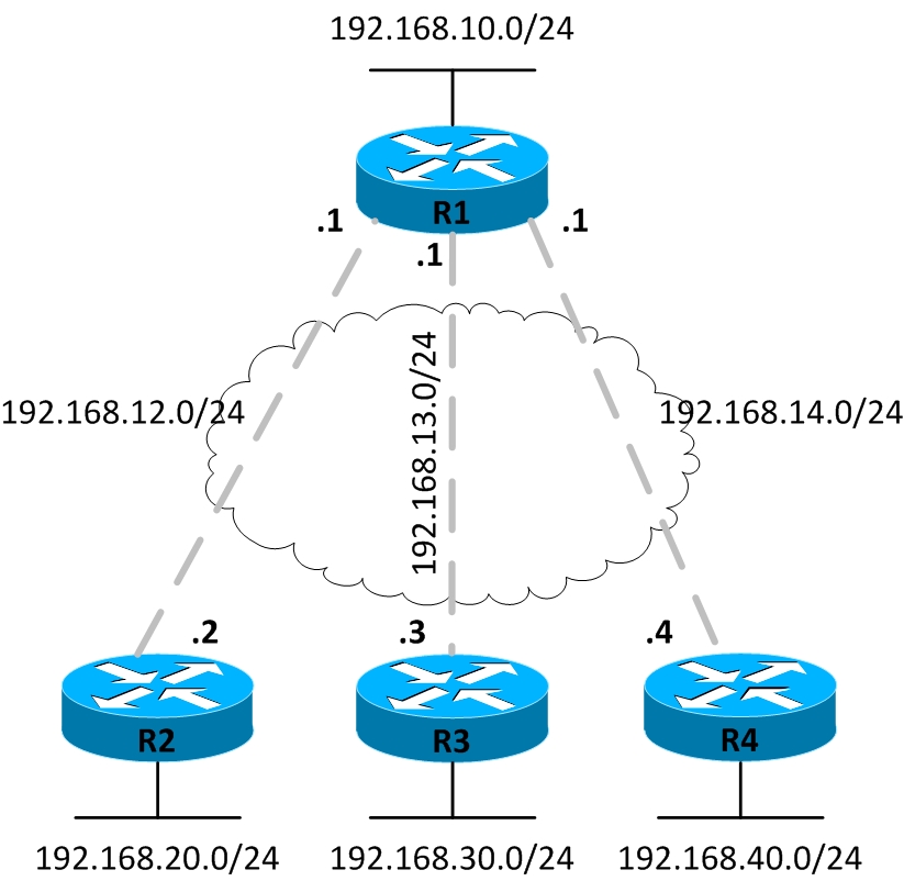
The second alternative of having one IP subnet per VC, works better for a partially meshed Frame Relay network, like the one shown in Figure 12-13. This is the more prevalent Frame Relay network because most organizations have a large number of remote sites that need to connect to a central site to access applications. Here there is no VC, for example, between R2 and R3 and so R2 cannot communicate directly with R3.
Figure 12-15 One Subnet per VC

You may have noticed that R1 has three IP addresses associated with it. Cisco IOS software allows you to create logical subdivisions of a physical interface, called subinterfaces. Subintefaces allow R1 to have three IP addresses associated with the same physical interface. The router can treat each subinterface and teh VC associated with it as a separate point-to-point serial link.
Also, we are using private IP addresses with predictabe /24 prefixes to enable you focus on underrlying concepts rather than numbers. However, you should keep in mind that on point-to-point subinterfaces you would usually see /30 addresses with 255.255.255.252 as subnet mask. This allows for only two valid IP addresses on a subnet and conserves available IP address space.
A Mix of Full and Partial Mesh
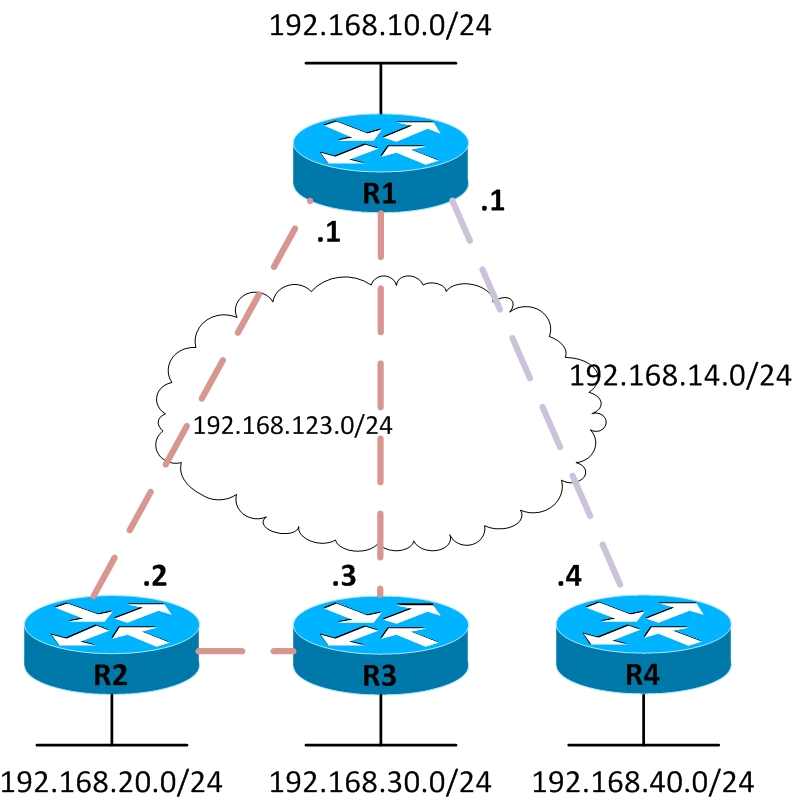
The third and last alternative for IP addressing is a mix of the first two alternatives. Figure 12-14 show a trio of routers R1, R2, and R3 with VCs in full mesh among them while a single VC to R4. In this case, you have two options for Layer 3 addressing. The first is to treat each VC as a separate Layer 3 subnet. However you would need four subnets for the Frame Relay netowrk in that case. The second option also shown here is to create a smaller full mesh between routers R1, R2, and R3 while leaving R4 out. This allows R1, R2, and R3 to use a single subnet, The VC between R1 and R4 is then treated as a separate subnetm, which results in only two subnets for the Frame Relay network rather than four.
Figure 12-16 A Mix of Full and Partial Mesh

In order to accomplish this addressing scheme, subinterfaces are used. Point-to-point subinterfaces are used when a single subnet is mapped to a single VC, for example, between R1 and R4. Multipoint subinterfaces are used when more than two routers are in the same subnet, for example, with R1, R2, and R3.
Multipoint interfaces can terminate more than one VC, and the term multipoint refers to the fact that more than one remote sites may be reachable off the interface.
We will provide you full configurations for all three scenarios discussed so far in the next section.
